UHF RFID technology, with its long-range identification, high-speed data transmission, and batch reading capabilities, has become one of the core technologies of modern IoT systems. As a key component of RFID systems, antenna performance directly determines system recognition efficiency, stability, and application scope. This post comprehensively explores the technical principles, selection methods, and design optimization strategies of UHF RFID antennas, covering a complete knowledge system from fundamental theories to practical applications. We will delve into the key parameters affecting antenna performance, compare the characteristics of different antenna types, and showcase how to optimize antenna selection and design based on specific application scenarios through case studies.
Fundamentals of UHF RFID Antenna Technology
UHF RFID systems operate in the 860MHz to 960MHz frequency band. Unlike LF and HF RFID systems, UHF RFID relies on electromagnetic radiation rather than inductive coupling for communication. This enables working distances of several meters or more. UHF RFID offers unique advantages:
l A shorter wavelength (about 30cm) allows for smaller antenna sizes, facilitating integration into various devices.
l Strong diffraction capability enables signals to penetrate non-metallic materials, making it suitable for object identification in complex environments.
However, in metal or liquid environments, the primary challenge for UHF RFID is signal attenuation. This occurs because metal surfaces reflect RF signals, while liquids may absorb part of the RF energy, thereby affecting communication performance.
According to Maxwell’s electromagnetic field theory, when a reader antenna emits electromagnetic waves, the tag antenna induces a current through electromagnetic coupling, powering the tag chip and establishing a communication link. This process involves complex impedance matching and energy coupling mechanisms, requiring precise control of antenna parameters for optimal performance.
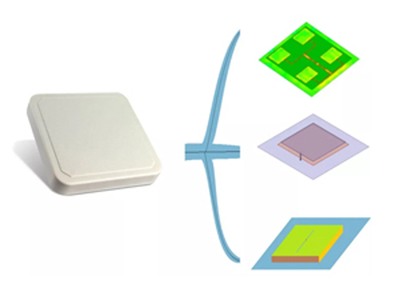
The antenna's radiation pattern determines how energy is distributed in space, directly affecting the reading range and directivity of the system. The radiation pattern mainly depends on the antenna type. UHF RFID antennas come in various forms, including dipole antennas, microstrip patch antennas, and array antennas. Each type has unique characteristics suited to different applications:
Dipole antennas: Simple structure, low cost, suitable for general item tracking.
Microstrip patch antennas: Compact size, easy integration, ideal for small devices.
Array antennas: Provide precise beam control and extended reading range.
Key Performance Parameters of UHF RFID Antennas
The performance of UHF RFID antennas is determined by several technical parameters. Understanding these parameters and their interrelations is essential for antenna selection and system design.
Operating Frequency
UHF RFID typically operates in the 860-960MHz band. Different countries and regions have varying regulations on specific frequency bands and power limits. Proper frequency matching ensures effective energy radiation and stable signal transmission. Mismatched frequencies cause impedance mismatch, leading to energy reflection and reduced read range.
Antenna Gain
Gain measures the radiation efficiency in the main lobe direction compared to an ideal point source antenna. Higher gain antennas focus energy more effectively in a specific direction, increasing read distance. Example: In warehouse shelf management, high-gain directional antennas ensure precise reading while avoiding misreads from adjacent shelves. However, excessive gain may result in overly narrow beams, requiring a balance between antenna count and coverage.
Beamwidth
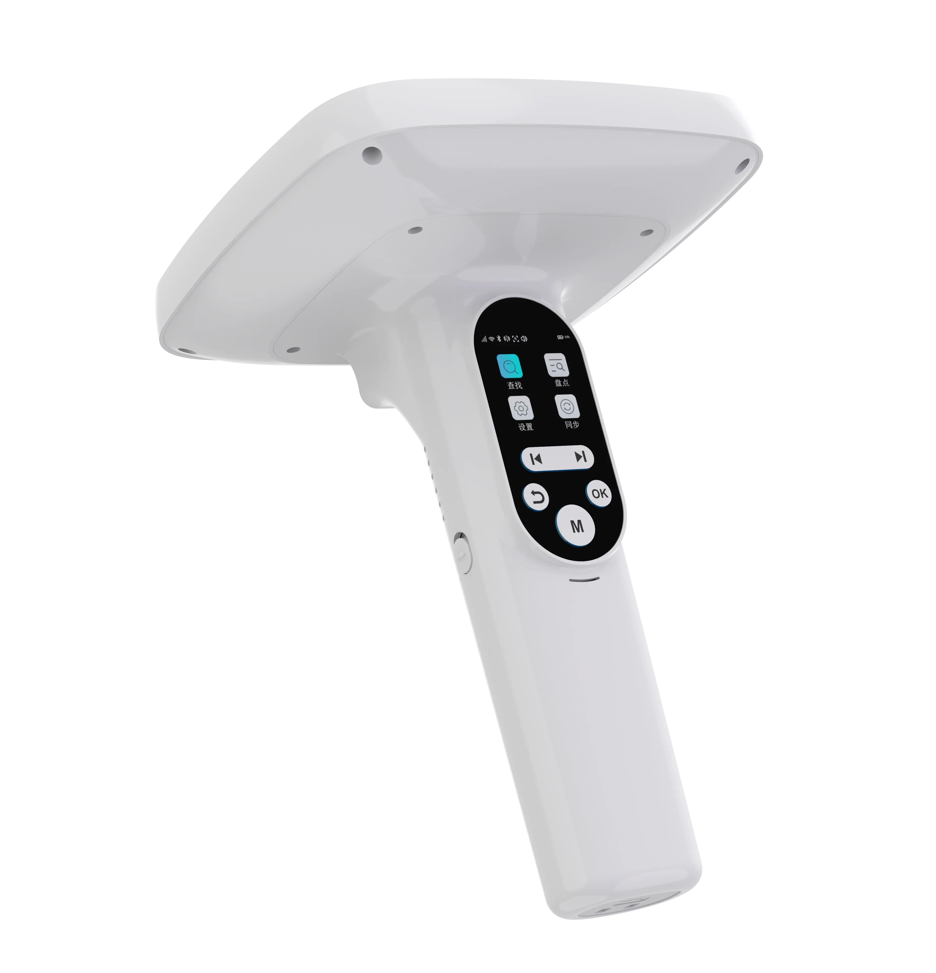
Describes the angular range of radiation power where it drops to half of the peak value.Wide beam antennas cover large areas, while narrow beam antennas enable precise identification. For example, Handheld antennas typically have a broad beamwidth for inventory counting. Narrow beam antennas (BRA-08, BRA-16) are widely used in retail store entrance security.
Polarization Mode
Defines the vibration direction of the electric field vector in electromagnetic waves. Two main types: Linear polarization (horizontal or vertical) and Circular polarization.
Linear polarization: Lower cost, longer read distances when aligned with the tag's polarization but requires fixed tag orientation.
Circular polarization: Shorter read range but does not depend on tag orientation, making it suitable for applications with random tag orientations.
Physical Characteristics
Includes size, material, and environmental adaptability.
Size: Larger antennas typically provide higher gain.
Material impact: Low-loss materials improve performance but increase costs.
Environmental resistance: Outdoor parking management requires waterproof and temperature-resistant antennas. Industrial production lines demand vibration resistance and EMI shielding.
|
Parameter
|
Definition
|
System Impact
|
Typical Value
|
|
Operating Frequency
|
Optimal working band of the antenna
|
Determines system compliance and regional applicability
|
860-960MHz
|
|
Gain
|
Main lobe radiation intensity
|
Affects read distance and directionality
|
6-10dBi
|
|
Polarization Mode
|
Orientation of the electric field vector
|
Affects tag reading dependency on orientation
|
Linear/
Circular
|
|
Bandwidth
|
Frequency range for stable performance
|
Determines frequency adaptability and stability
|
20-50MHz
|
Understanding these parameters enables informed antenna selection and system optimization. In real-world engineering, balancing these factors ensures optimal performance and cost efficiency.
UHF RFID Antenna Types and Characteristics
UHF RFID antennas vary based on application scenarios and performance requirements:
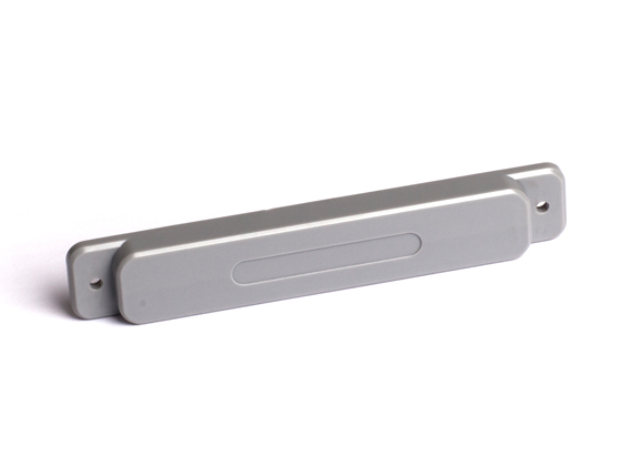
Dipole Antennas
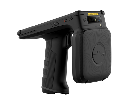
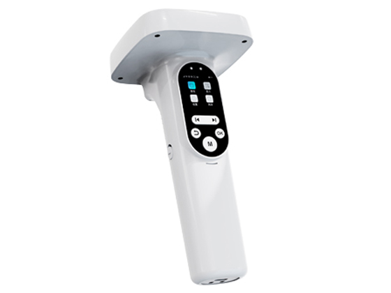
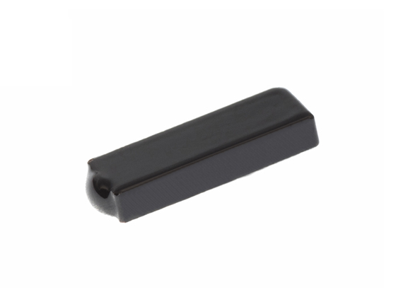
The most common type. Simple, cost-effective, and suitable for 360° coverage, such as handheld inventory devices. Standard dipoles are large, making them less suitable for small devices. Modified curved designs optimize impedance matching for compact applications like asset management.

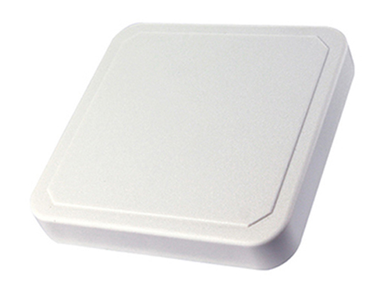
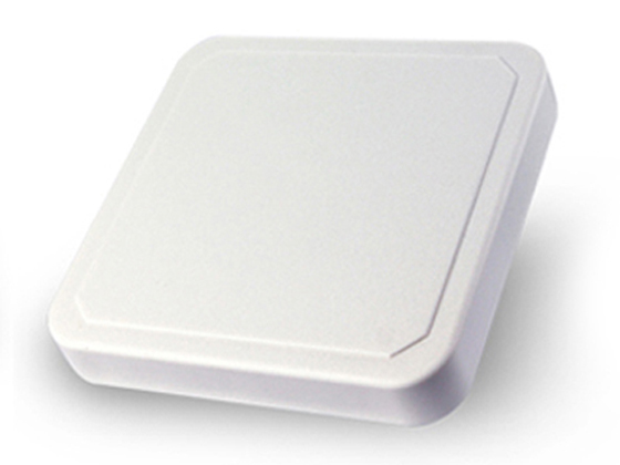
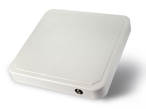
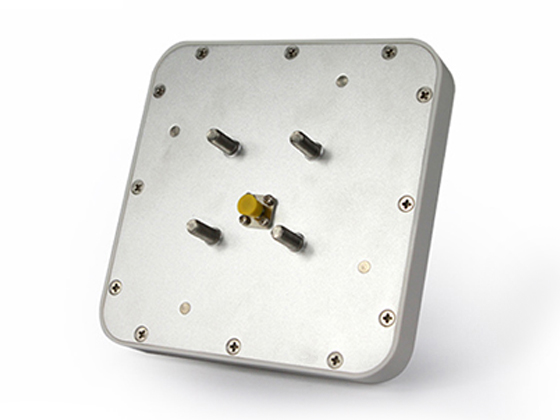
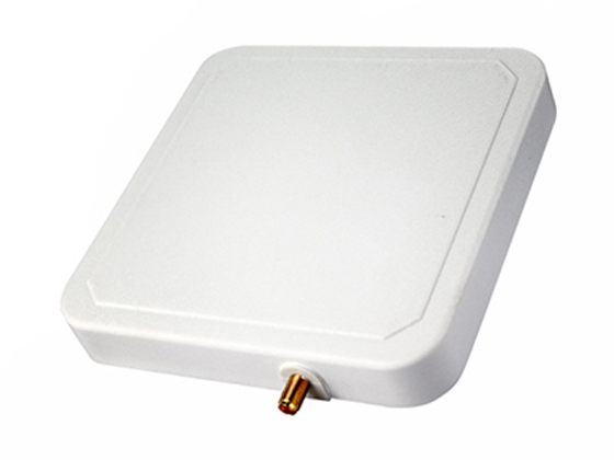
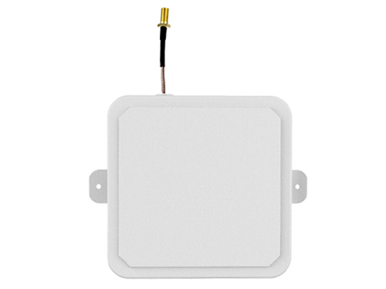
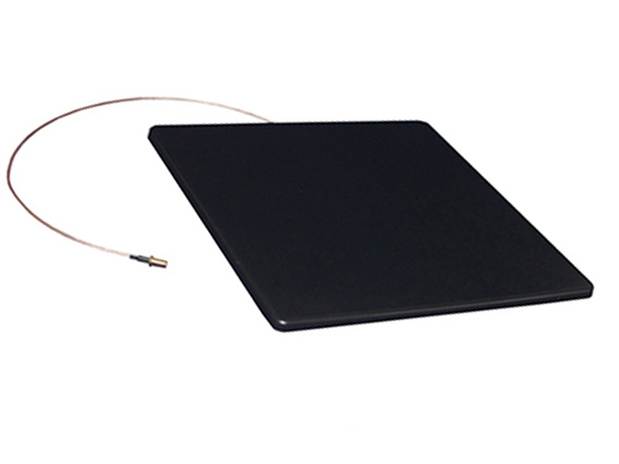
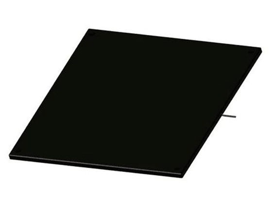
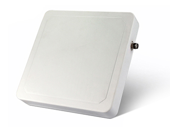
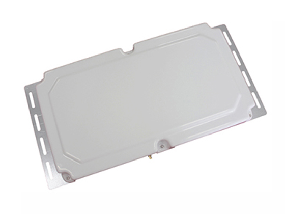
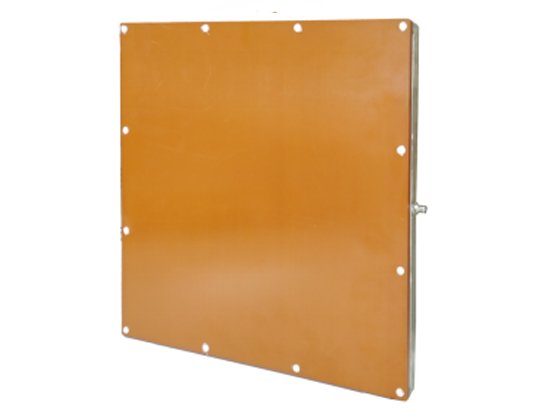
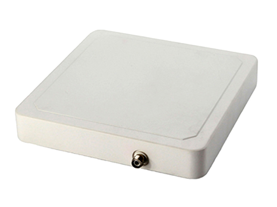
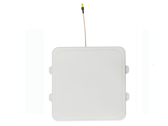
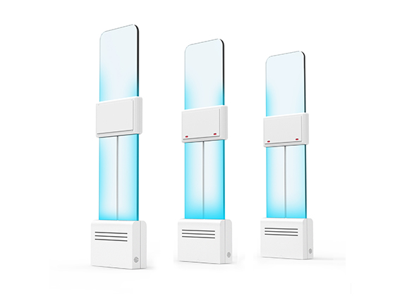
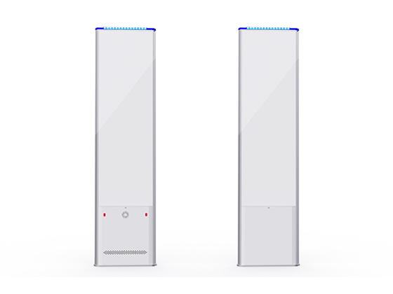
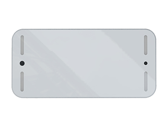
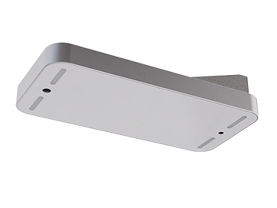
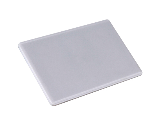
Microstrip Patch Antennas
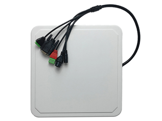
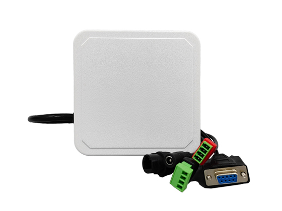
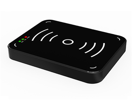
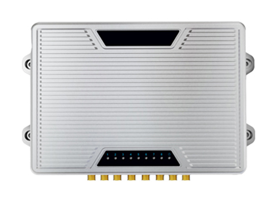
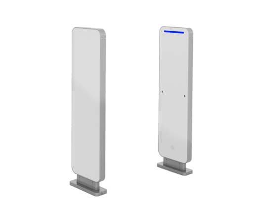
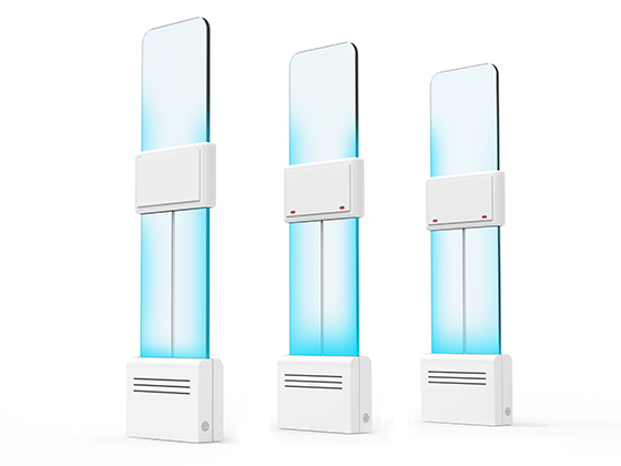
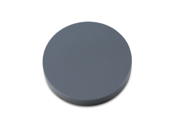
Composed of a metal patch, dielectric substrate, and ground plane. Low-profile, lightweight, easy integration, and good directivity. Optimizable via shape, size, and substrate material adjustments. Suitable for integrated reader and smart gate reader systems.

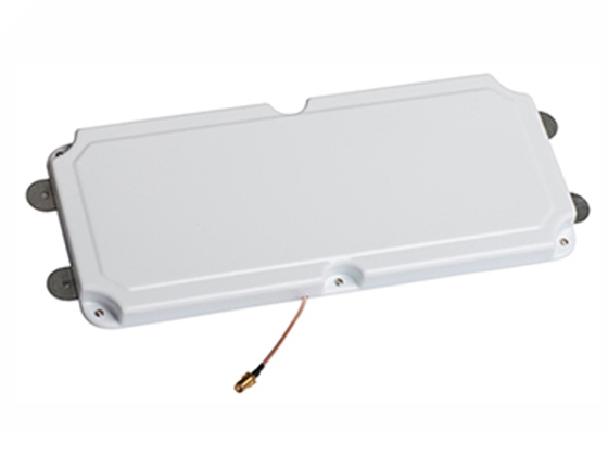
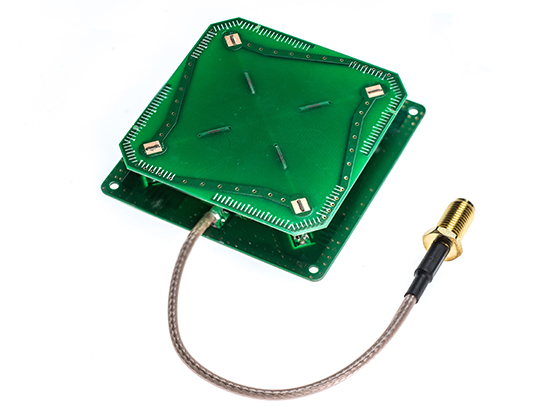
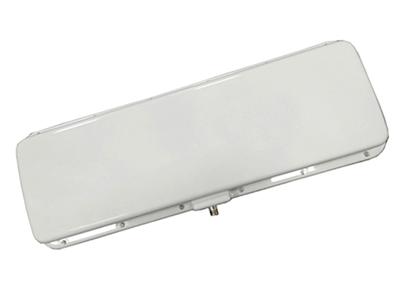
Array Antennas
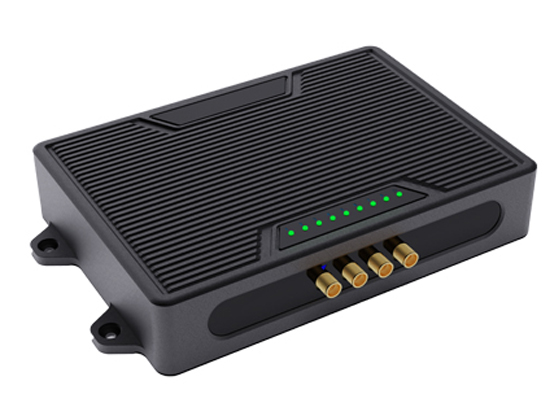
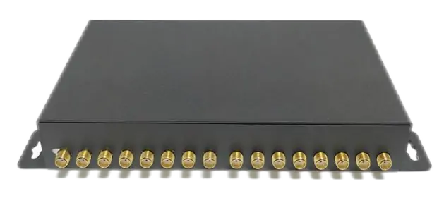
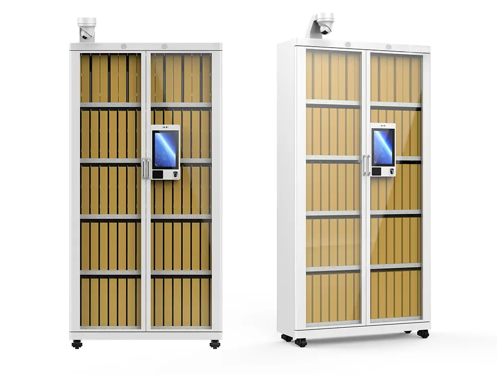
Made of multiple radiating elements. High gain and beamforming capabilities for long-distance identification and precise spatial control (e.g., smart parking management). More complex structure, higher cost, and requires phase control circuits.

UHF RFID Antenna Selection Strategy
Antenna selection begins with application scenario analysis. Different industries demand different technical specifications. Such as, retail inventory management needs wide beam and wide band antenna. Manufacturing tracking application needs directional and interference resistance antenna.
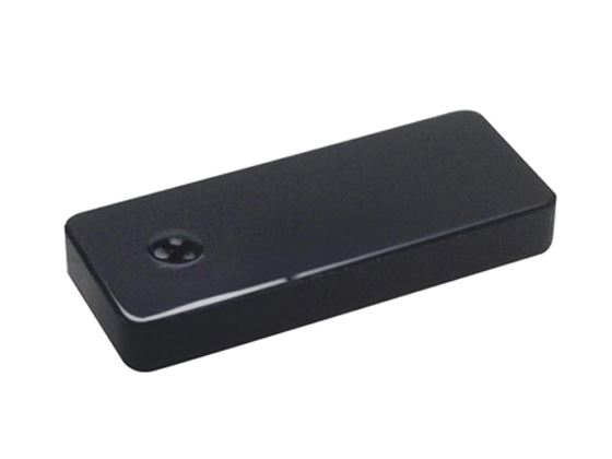
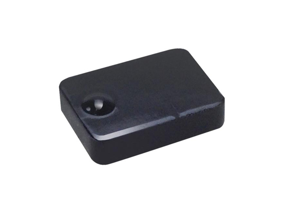
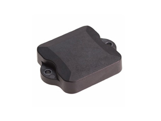
Environmental adaptability is crucial. Factors like metal, liquid, and electromagnetic interference impact performance. Solutions include anti-metal antennas or optimized installation strategies. Industrial applications require waterproofing and temperature resistance.
Read range requirements correlate with antenna gain. Higher gain extends range but narrows beamwidth, necessitating a balance: Library management uses 6-8dBi wide-beam antennas (e.g., BRA-01, BRA-02 series). Parking management uses 10-12dBi narrow-beam antennas.
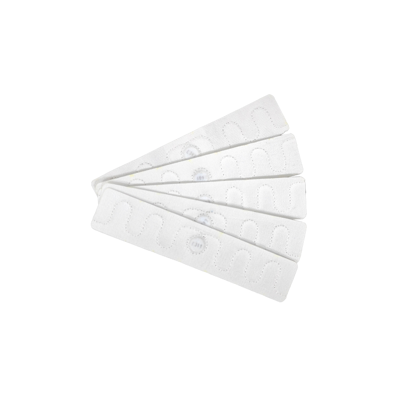
Polarization matching depends on tag orientation. Linear polarization antenna (BRA-49, BRA-01L) is the best choice for fixed-direction tags (e.g., vehicle windshield tags); Circular polarization antenna (BRA-01CR, BRA-15) is the best for random orientations (e.g., retail clothing tags).
A cost-benefit analysis is essential throughout the selection process, considering total cost of ownership (TCO). High-performance antennas may reduce device count, lower maintenance costs, and enhance economic viability.
UHF RFID Antenna Design Process
The design of UHF RFID antennas is a complex multi-parameter optimization process that requires comprehensive consideration of electromagnetic performance, physical structure, and practical application requirements. Modern antenna design typically starts with requirements analysis, focuses on simulation optimization, and concludes with testing and validation.

Requirements Analysis:
Determine key antenna parameters:
Frequency: 902-928MHz
Reader antenna: High gain (8dBi), circular polarization
Size: ≤200*200*30mm
Environmental adaptability: IP54
Target price: 50 USD/piece
Based on requirements analysis, preliminarily determine antenna type: dipole, microstrip, or array.
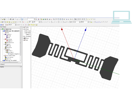
Simulation Design (HFSS/CST/ADS):
Modeling: Parametric structure (line width, length, spacing)
Materials: FR4 (ε=4.4), copper (5.8e7 S/m)
Optimization goals: S11 < -10dB, radiation efficiency > 70%
Radiator simulation → Feed network simulation → Co-simulation
Fabrication & Testing:
Test items: Impedance (network analyzer), read range (anechoic chamber)
Finally, testing and validation (read distance, multi-tag reading, interference resistance, long-term stability) ensure correct selection and system optimization.